How does modal dispersion limit throughput over multimode fibers?

The optical fiber is a widely used method for carrying information due to its small size, low linear losses, insensitivity to electromagnetic disturbances, etc. However, the fiber possesses intrinsic performance limitations which are inherent to its physical properties.
More specifically, for multimode optical fibers installed starting from the 80’s and 90’s, such as OM1 (62.5/125 µm) and OM2 (50/125 µm), high-speed transmission is limited as a result of modal dispersion.
Let’s take a look at this in further detail. Watch this 2-minute video and discover how the phenomenon of modal dispersion works:

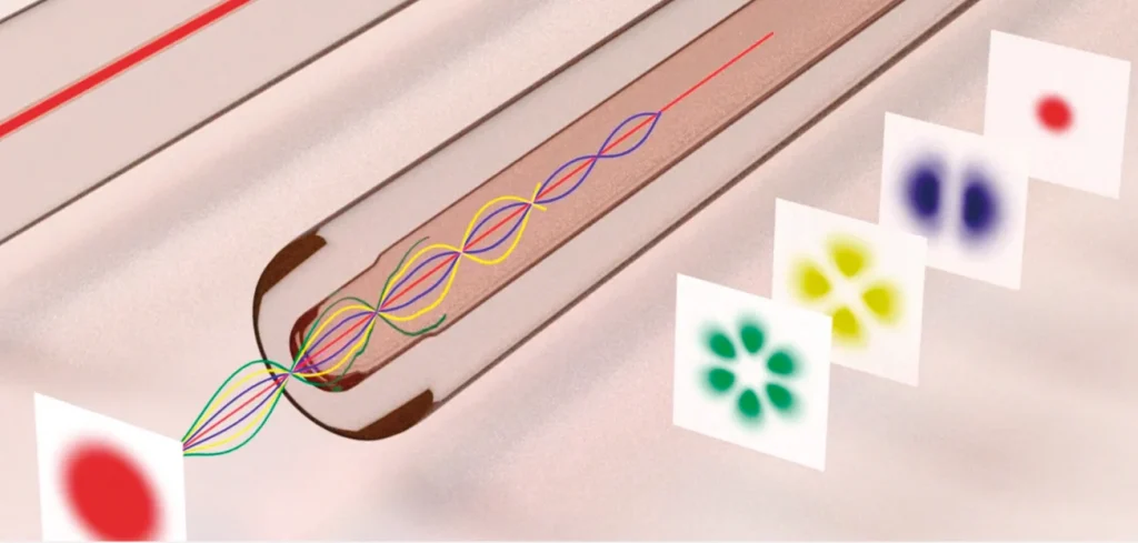
A standard multimode fiber with an index gradient profile, OM1-2-3-4-5 type, has linearly polarized modes known as LP with degenerate propagation constants LPi, j. Degenerate modes couple very strongly within their mode group. Conversely, modes from different mode groups are more isolated and can therefore be considered independent transmission channels within the same optical fiber.
A conventional multimode fiber can typically support dozens of modes, divided into a few groups of modes. Below are some examples of mode intensity profiles for a multimode optical fiber.

Modal dispersion is a distortion mechanism occurring in multimode fibers. Due to the different velocities of the modes, the signal is spread out and often deformed in time during the propagation in the fiber.

Let us go back to the physical properties of multimode fibers so that we can analyze this phenomenon in more detail. When the light from the transceiver enters the multimode fiber, it “splits” into different rays called “modes.”
The light rays from the source enter the fiber core with different angles relative to the optical fiber axis. The rays that enter with a smaller angle are going to travel through the fiber along a more direct path in relation to rays that enter with a larger angle and are going to reflect themselves many more times during propagation.
Thus, each mode travels the length of a different optical path within the optical fiber. As a result, the time it takes to arrive at the end of the fiber differs according to the mode. This is known as DMD or Differential Mode Delay.

The non-simultaneous arrival of different components of the signal deforms the shape of the signal that was initially sent: as a result of DMD, an emission pulse can spread during propagation in the multimode spectrum or, in extreme cases, split into two independent pulses.
This leads to inter-symbol interference and the inability to retrieve the data that was weakly transmitted. The higher the transmitted throughput is, the greater the distortion is; that is, the light pulses are short and close (typically 100 ps between each pulse at 10 Gb/s).
To sum up, DMD degrades the width of the bandwidth capacity of the optical fiber. For a given throughput, it reduces the distance that can be reliably attained between transmitter and receiver.

The refractive index profile of the fiber strongly impacts the velocity of the different modes of propagation, causing modal dispersion. This is why there are different generations of graded-index multimode fibers (OMx, x = 1, 2, 3 or 4), which decrease the group time differences between modes according to the fiber type.
Note: It is interesting to note that when the transverse dimensions of the fiber are small enough to allow for the propagation of only one mode, optimal dispersion conditions are then obtained to minimize the spreading of the light signal in time during propagation. This is known as a “single-mode fiber.”
These different generations of multimode fibers therefore have different bandwidths. Depending on the fiber generation, the achievable distances for a given throughput have been summarized in the article Is your network cabling infrastructure limiting your productivity?
Today, however, there is an innovative solution that allows you to conserve your existing multimode cabling infrastructure while meeting the growing demand for increased network bandwidth. This passive solution makes it possible to increase the bandwidth of multimode optical fibers by overcoming the obstacle of modal dispersion.
If you’d like to know more about the AROONA product line and the technology that converts your multimode fibers into single-mode fibers, then download our white paper on this topic to find out more.
Quick, come check out the AROONA range and its many case studies.

Par Kévin Lenglé
Kevin Lengle, who’s worked as a researcher at the CNRS (French National Research Center) and a telecom equipment manufacturer, holds a Master’s degree in Engineering from the National School of Applied Sciences and Technology and a Ph.D. in Physics. He’s been working at Cailabs as a Product Line Manager since 2015, bringing his expertise in optics and telecommunications to the development and commercialization of innovative optical solutions to fully harness the potential of multimode optical fibers.


